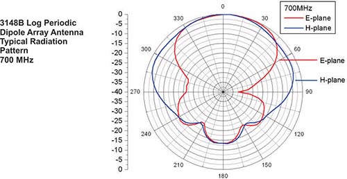
log periodic antenna radiation pattern
For log-periodic dipole arrays the impedance values range from about 60 to 100 ohms. So if anyone with experience in this area could maybe check the project and tell.

Simulated And Measured E Plane Radiation Pattern Of The Designed Lpda Download Scientific Diagram
That is the Log-Periodic Spiral Antenna has a theoretical impedance of about 188 Ohms.
. Optimized for radiomonitoring and measurements. Log periodic antenna 1. Log Periodic Dipole Array Antenna.
The antenna is optimized for radiomonitoring and measurements. The radiation patterns are virtually frequency-independent and the sturdy design makes it suitable for stationary and mobile use. The radiation pattern of the Log-Periodic Spiral Antenna is approximately given by.
Comparison between simulations and measurements c. Its impedance directional patterns and directivity are constant with frequency. The energy being radiated is represented by the patterns drawn in a particular direction.
It is termed a log-periodic dipole array and derives its name from the fact that its important characteristics are periodic concerning the logarithm of the frequency. Our Linear Polarized Log-Periodic Antennas ANT-LPA are dipole arrays designed to have nearly constant gain and input impedance over a broad frequency range. The cost of these equipment increases substantially with the demand of precision in the output.
The individual compon. Calculate the radiation pattern and input impedance for a log periodic dipole array LPDA antenna. It is a directional antenna so its radiation pattern is also uni-directional.
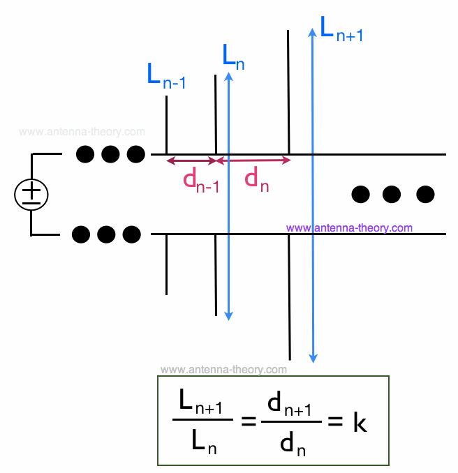
The vertical log-periodic antenna is characterised by a radiation pattern that is essentially constant at all frequencies. Log Periodic Antenna Keval Patel 100110111007 2. This means that each dipole is 25 longer than the one to the left of it and the separation d between each dipole also increases by 25.
For the array in Figure 1 we use an expansion factor k 125. Let us look at the pattern of energy radiation. The Log-periodic Antenna is useful for any application where linearly polarized radiation moderate gain and stable impedance and radiation pattern performance over a wide bandwidth is required.
If you need assistance beyond what is provided above please contact us. Through the use of a Guidelines Check built into the software. Its SWR with a given feed line and the strength of its radiation pattern.
For example lpdipole lpda BoardLength02 creates a printed log-periodic dipole array with a board length of 02 m. My problem is that I cant get the same results as i got with 4NEC2 and EZNEC. Introduction In telecommunication a log-periodic antenna is a broadband multi- element directional narrow-beam antenna that has impedance and radiation characteristics that are regularly repetitive as a logarithmic function of the excitation frequency.
Popular applications include terrestrial television EMC measurement wireless communications and electronic warfare. Spacing between the feeders booms is generally set to give an impedance in the order of 100 ohms. And particular for mobile communication bands from 1150 MHz up to 2450 MHz.
Radiation patterns of a log-periodic antenna in the vhf band. Non-radiating transmission lines are used to model the boom of the LPDA antenna. The figure given above shows radiation pattern of a dipole antenna.
This is true of its impedance. The RSHL223 log-periodic antenna covers a very wide frequency range from 200 MHz to 13 GHz. In actual realizations of Spiral antennas the impedance tends to be less than this in the 100-150 Ohm range.
Current laboratory setup for performing radiation pattern measurement of any antenna is composed of signal generators and a spectrum analyzer. In Figure 1 we show the basic 5 element Log-Periodic Dipole Antenna Array. The antenna comprises a curtain of dipoles insulated into sections and suspended from a support mast.
The vertical log-periodic antenna is designed for direct connection to a 300 ohm balanced open wire feeder or a 50 ohm. It is a broadband antenna. In this paper the analysis design and simulation of log periodic dipole antenna LPDA is presented which is suitable.
Log Periodic Dipole Array with 5 Arms. The radiation pattern measurements and numerical computations of gain in wide frequency range. I have to simulate the radiation pattern of the LPDA antenna at 670MHz E and H-Plane.
The Radiation pattern of log-periodic antenna can be of uni-directional or bi-directional depending upon the log periodic structures. The radiation patterns and gain at 200 500 700 and 1000 MHz are shown both as elevation and azimuth patterns in Figure 6. Lpdipole lpda NameValue sets properties using one or more name-value pairs.
Im new to hfss and this is my first project. Log periodic antennas can be particularly challenging to model. Lpdipole lpda creates a printed log-periodic dipole array antenna using default property values.
I have uploaded my project and the 4NEC2 results. A good impedance match VSWR. As ψ is increased from 0 to 50 the impedance increases to approximately 160 ohms.
Radiation Patterns are diagrammatical representations of the distribution of radiated energy into space as a function of direction. The design simulation and experimental investigation of a triple-band Log-Periodic Dipole Antenna is presented. The most elementary form of log-periodic antenna is shown in Figure 1 a.
In this paper the radiation pattern measurement of a log-periodic antenna is done on a new platform consists. For uni-directional Log-periodic antenna the radiation towards shorter element is of considerable amount whereas in. There are a variety of log-periodic structures and all of them are not frequency-independent.

The Geometry And Radiation Patterns Of The 17 Element Log Periodic Download Scientific Diagram
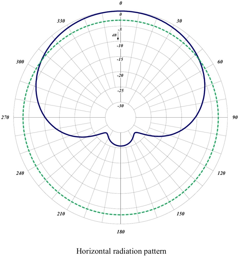
655 70 Log Periodic Antenna Vhf Comprod Inc

What S The Difference Between An Lpda Antenna And A Yagi Antenna Antenna Cell Phone Signal Booster Dipole Antenna

Simulacion De Antena Plano De Tierra Ground Plane Para Fm Con 4nec2 Chart Line Chart Diagram

Design And Analysis Of Modified Log Periodic Dipole Antenna With Enhanced Gain Semantic Scholar
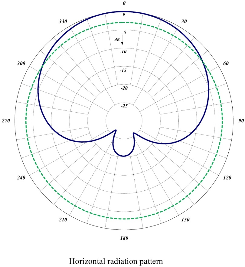
465 70 Log Periodic Antenna Uhf Comprod Inc

Dual Polarized Log Periodic Antennas Antenna Products
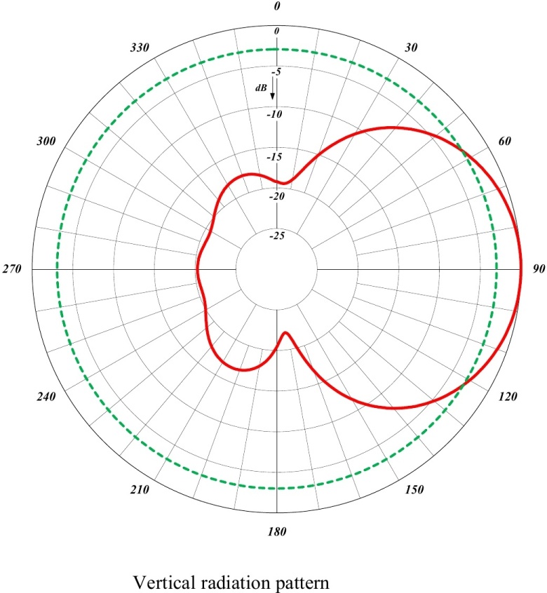
465 70 Log Periodic Antenna Uhf Comprod Inc

Simulated And Measured Radiation Patterns Of The Log Periodic Antenna Download Scientific Diagram

Measured Normalized Radiation Patterns Of A Euclidean And B Meander Download Scientific Diagram
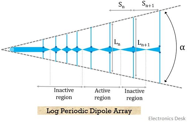
What Is Log Periodic Antenna Working Characteristics Advantages Disadvantages And Applications Of Log Periodic Antenna Electronics Desk

Log Periodic Tooth Antennas Antennas Period Teeth
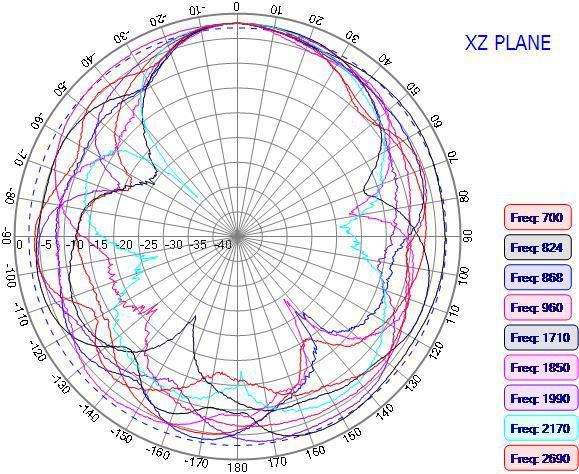
Antenna Radiation Patterns H Plane E Plane Xy Xz Yz Planes Data Alliance Net

Understanding Antenna Gain Telewave Inc
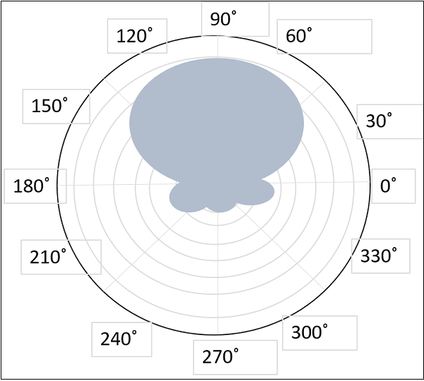
Antenna Theory Log Periodic Antenna

Log Periodic Antennas Antenna Products
